Categories Control, Profile Controllers
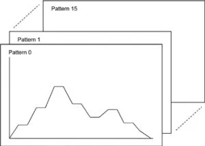
- Program capacity with 16-patterns, 16-steps
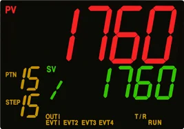
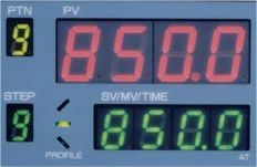
- Easily legible LCD display with 11-segment characters
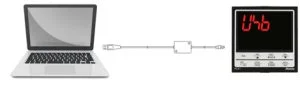
- Efficient Monitoring software
- Enhanced serial communication function
- Drip-proof/Dust-proof (IP66)
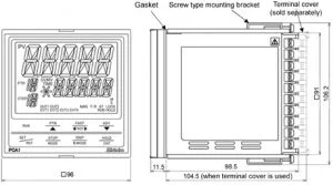
- Dimensions
- Specifications
Brand : Shinko