Categories Control, Profile Controllers
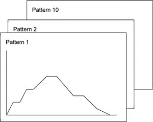
- Program capacity with 10-patterns, 10-steps/pattern
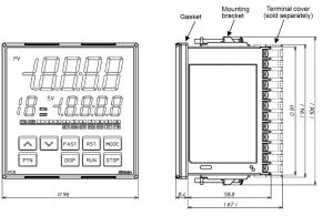
- Easier viewing large display
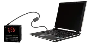
- Power supply and quick setup using the Tool cable and USB cable
- Drip-proof/Dust-proof (IP66)
- External dimensions
- Specifications
Brand : Shinko