| Name |
Digital Indicating ORP Meter |
| Model |
(*) Power supply voltage 100 to 240 V AC is
standard.
When ordering 24 V AC/DC, enter 1 in Power supply
voltage, after ORP.
| AER - 1 0 |
1 |
-ORP |
|
,
|
|
| Input points |
1 |
|
|
|
1 point |
| Input |
ORP |
|
|
ORP Combined Electrode Sensor |
| Power supply voltage |
|
|
100 to 240 V AC (Standard) |
| 1 |
|
24 V AC/DC (*) |
| Option |
| C5 |
Serial communication RS-485 |
| EVT3 |
EVT3, EVT4 outputs (Contact output 3, 4) |
|
| Measurement range |
-2000 to 2000 mV Resolution: 1 mV |
| Repeatability |
Within ± 5 mV (at equivalent input) |
| Linearity |
Within ± 5 mV (at equivalent input) |
| Input sampling period |
125 ms |
| Time accuracy |
Within ± 1% of setting time |
| ORP inputs for moving average |
1 to 120 times |
| Contact output |
Relay contact 1a
Control capacity: 3 A 250 V AC (Resistive load), 1 A
250 V AC (Inductive load, cos =0.4)
Electrical life: 100,000
cycles
Output action: P control, ON/OFF control |
| Transmission output |
Converting ORP value or MV to analog signal every input sampling period,
outputs the value in current.
If Transmission output high limit and
low limit are set to the same value, Transmission output
will be fixed at 4 mA DC.
Bar graph indication is possible in
accordance with transmission output.
Resolution: 12000
Output: 4
to 20 mA DC (Load resistance: Max. 550 Ω )
Output accuracy: Within ±
0.3% of Transmission output span |
| Self-diagnosis |
The CPU is monitored by a watchdog timer, and if an abnormal status
occurs, the instrument is switched to warm-up status. |
| Ambient temperature |
0 to 50 0C |
| Ambient humidity |
35 to 85 %RH (Non-condensing) |
| Power supply voltage (user-specified) |
AER-101-ORP: 100 to 240 V AC 50/60 Hz Allowable fluctuation range: 85 to
264 V AC
AER-101-ORP 1: 24 V AC/DC 50/60 Hz Allowable fluctuation
range: 20 to 28 V AC/DC
|
| Structure |
Flush (Applicable panel thickness: 1 to 8 mm)
Case: Flame-resistant
resin
Color: Black
Front panel: Membrane
sheet
Drip-proof/Dust-proof IP66 (for front panel only)
|
| Protection structure |
Overvoltage category II , Pollution degree 2 (IEC61010-1) |
| Safety standards |
RoHS directive compliant |
| Dimensions |
W48 x H96 x D110 mm, Case depth: 98.5 mm (when mounted through a control
panel) |
| Weight |
Approx. 280 g |
| Serial communication [C5 option] |
The following operations can be carried out from
an external computer.
- Reading and setting of various data
- Reading of the ORP value and status
- Function change, adjustment
- Reading and setting of user save area
| Cable length |
1.2 km (Max.), Cable resistance value: Within 50 Ω
(Terminators are not necessary, but if used, use 120
Ω minimum on both sides.)
|
| Communication line |
EIA RS-485 |
| Communication method |
Half-duplex communication |
| Communication speed |
9600, 19200, 38400 bps (selectable by keypad) |
| Synchronization method |
Start-stop synchronization |
| Code form |
ASCII, Binary |
| Communication protocol |
Shinko protocol, MODBUS ASCII, MODBUS RTU
(selectable by keypad) |
| Data bit/Parity |
8-bits/No parity, 7-bits/No parity, 8-bits/Even,
7-bits/Even, 8-bits/Odd, 7-bits/Odd (Selectable by
keypad) |
| Stop bit |
1, 2 (Selectable by keypad) |
| Error correction |
Command request repeat system |
| Error detection |
Parity check, Checksum (Shinko protocol),
LRC (MODBUS protocol ASCII), CRC-16 (MODBUS protocol
RTU) |
Data Format
| Communication Protocol |
Shinko Protocol |
MODBUS ASCII |
MODBUS RTU |
| Start bit |
1 |
1 |
1 |
| Data bit |
7 |
7 (8) Selectable |
8 |
| Parity |
Even |
Even (No parity, Odd) Selectable |
No parity (Even, Odd) Selectable |
| Stop bit |
1 |
1 (2) Selectable |
1 (2) Selectable |
|
| EVT3, EVT4 outputs (Contact output 3, 4) [EVT3 option] |
Same as Contact output |
| Dimensions, Panel cutout (Scale: mm) |
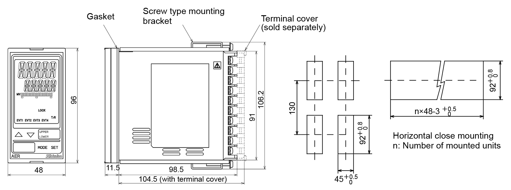 |
| Terminal arrangement |
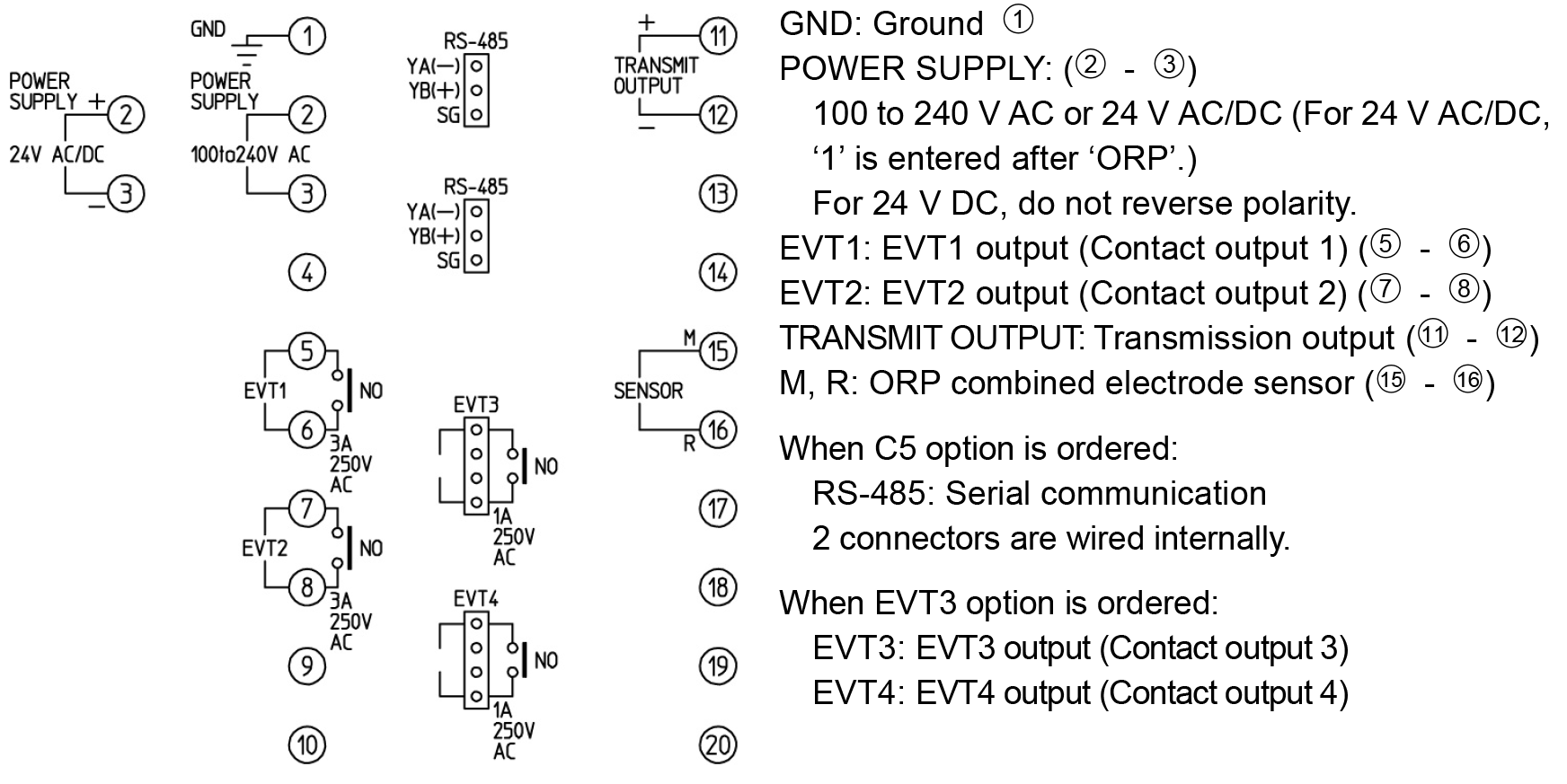 |
