Description
| Features | ||
|---|---|---|
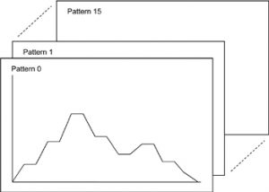
| Program capacity with 16-patterns, 16-steps | Program capacity: 16-patterns, 16-steps Program control of up to 256 steps is possible by linking patterns.
|
|
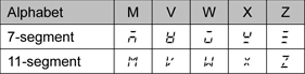
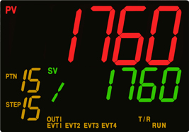
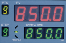
| Easily legible LCD display with 11-segment characters | 11-segment character LCD display is used, so characters can be read easily.
PCA1 and PC-900 comparison
PC-900
PV color changes linked with alarm Backlight indication time |
|
| Efficient Monitoring software | Monitoring software (SWM-PCA01M) is available for data monitoring, editing, loading, etc. Power to the PCA1 is not required if USB communication cable (CMB-001) is used.  |
|
| Enhanced serial communication function | Communication protocol: Shinko protocol, Modbus ASCII , and Modbus RTU Modbus ASCII, Modbus RTU: A maximum of 100 pieces of multiple data Read/Write is possible. |
|
| Drip-proof/Dust-proof structure | IP66 (for front panel only), usable in harsh environments where dust is present or water splashes. | |
| Dimensions | 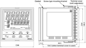 |
|

| Specifications | ||
|---|---|---|
| Input | Thermocouple | K, J, R, S, B, E, T, N, PL-II, C(W/Re5-26) External resistance: 100 Ωmax. However, B input: External resistance: 40 Ωmax. |
| RTD | Pt100, JPt100 3-wire type Allowable input lead wire resistance: 10 Ωmax. per wire However, Pt100, -100.0 to 100.0 : 5 max. per wire |
|
| Direct current | 0 – 20 mA DC, 4 – 20 mA DC Input impedance: 50 Ω Allowable input current: 100 mA max. |
|
| DC voltage | 0 – 10 mV DC, -10 – 10 mV DC, 0 – 50 mV DC, 0 – 100 mV DC, 0 – 1 V DC: Input impedance: 1 MΩ min. Allowable input voltage: 5 V DC max. Allowable signal source resistance: 2 k Ωmax. (0 – 1 V DC) 200 max. (0 – 100 mV DC, 0 – 50 mV DC) 40 max. (-10 – 10 mV DC) 20 max. (0 – 10 mV DC) 0 – 5 V DC, 1 – 5 V DC, 0 – 10 V DC Input impedance: 100 k min. Allowable input voltage: 15 V DC max. Allowable signal source resistance: 100 max. |
|
| Output | ||
|---|---|---|
| Control output | Relay contact 1a1b | Control capacity: 3 A 250 V AC (resistive load) 1 A 250 V AC (Inductive load cos=0.4) Electrical life: 100,000 cycles |
| Non-contact voltage (For SSR drive) |
12 V DC15% Max 40 mA (Short circuit protected) |
|
| Direct current | 4 to 20 mA DC Resolution: 12000 Load resistance: Max 600 |
|
| Event output EV1 – EV4 | Relay contact 1a | Control capacity: 3 A 250 V AC (resistive load) 1 A 250 V AC (inductive load cos=0.4) Electrical life: 100,000 cycles Event output EV3, EV4 share one common terminal. |
| Performance | ||
|---|---|---|
| Reference accuracy | Thermocouple | Within 0.2% of each input span1 digit However, R, S input 0 to 200 (32 to 392): Within 6 (12) B input, 0 to 300 (0 to 572): Accuracy is not guaranteed. K, J, E, T, N input, Less than 0 (32): Within 0.4% of input span1 digit |
| RTD | Within 0.1% of each input span1 digit | |
| Direct current,DC voltage | Within 0.2% of each input span1 digit | |
| Cold junction compensation accuracy | Within 1, at 0 to 50 | |
| Input sampling period | 125 ms | |
| Time indication accuracy | 0.1% of setting time | |
| Setting accuracy | Based on Reference accuracy and Cold junction compensation accuracy | |
| Time setting accuracy | 0.1% of setting time | |
| Setting resolution | Temperature | Thermocouple, RTD input without decimal point: 1°C (°F) Thermocouple, RTD input with decimal point: 0.1°C (°F) DC voltage, current input: 1 |
| Time | 1 minute or 1 second | |
| Program Performance | ||
|---|---|---|
| Number of patterns | 16 (Linkable) | |
| Number of steps | 256 (16 steps/pattern) | |
| Repetitions | 0 to 9999 times (Repetitions disabled when set to 0.) | |
| Program time range | 0 to 99 hours 59 minutes/step, or 0 to 99 minutes 59 seconds/step (When —– is set, Fixed value control is performed using step SV.) |
|
| Wait value | Thermocouple, RTD input without decimal point: (0 to 100)°C (°F) Thermocouple, RTD input with decimal point: (0.0 to 100.0)°C (°F) DC voltage, current input: (0 to 1000) (The placement of the decimal point follows the selection.) (The Wait action is disabled when set to 0 or 0.0.) |
|